![]()
Victorian Science Fiction: How To Build An Iron Ram
Let us consider the development of the navel Ironclad.
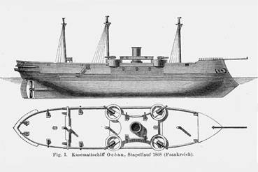
Here we have the deck plans for one of the transitional forms as the navel ship moved
from the sail powered vessel to the steam power.
More examples of these early Ironclads can be found at The First Ironclads.
I drew particular inspiration from:
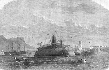
The French Taureau built in 1865, and
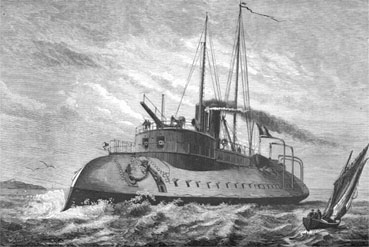
The French Le Taige built in 1871.
These vessels and others of the same type, known as Iron Rams, were the model from which I
have built my own.
I saw this model of the Captain Nemo's Nautilus from Joules Verne's 20,000 Leagues Under the Sea.

I thought the hull of this submarine might be made into two
water-line models of Iron Rams.
These were on close-out at K-B Toys, so I thought I would give it a go.
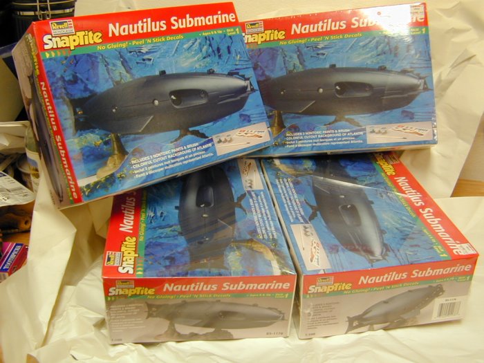
Being at a good price and not knowing how many I would want in the end, or how many I would
mess up before getting it right, I decided to clear the shelf.
The contents of the boxes were pretty basic.
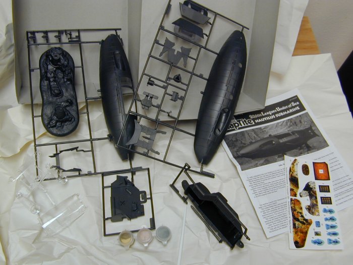
The box held: four sprues of parts in dark gray, one sprue of clear parts, a sheet of color peel and stick "decals",
a set of paints, a brush, and the instruction manual.
Most of this will not be very useful in this project, but may be worth holding on to.
The Plans:
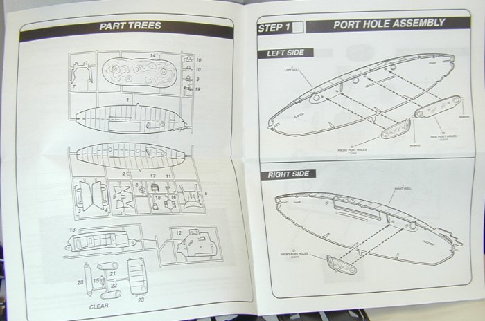
As I have no intention to follow the even plans these will not be very useful.
The Parts list:
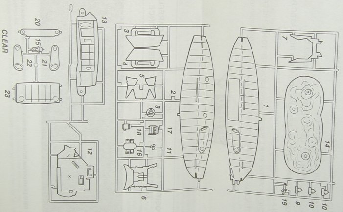
This has some use in planning on what I will be doing with these parts.
The painting set:
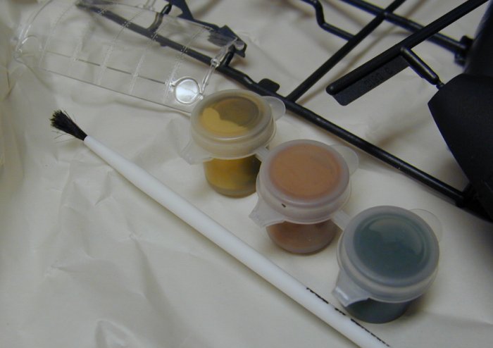
This may be useful in paining some terrain or buildings, but I am very skeptical as to their
use in painting a model.
The Brush:
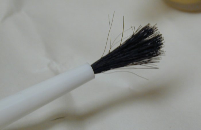
I think the quality of this brush says a lot about the care taken in putting this kit together.
We all have to start somewhere, but this is a pretty poor start. It might be useful from brushing
on PVA glue on to a figure's base from grassing
Well it looks like much of this will end up in the parts bin or the recycle bin.
But let us consider the main course, the plastic parts.
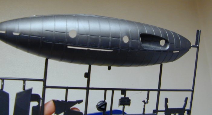
Sadly the model was designed with the main hull dividend side to side and not top to bottom.
This will make conversion to a water-line a bit more of a problem.
A good surprise:
The castings of the vessel have much more detail then the box art suggested.
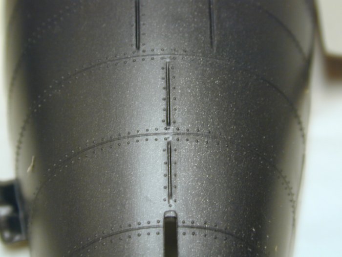
Rivets
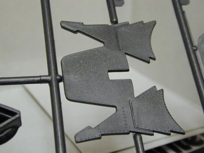
The rivet detail extended to some of the other parts as well.
While I may not use most of these in this project, it is nice to have a box of spare parts
with such details for future models.
Getting to work:
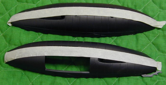
As the hull was cast with a left and right side, some provision needed to be made to allow the
model to appear as a vessel floating in water. I considered using the hull halves as they came,
but they did not have the kind of symmetry as seen in the historic vessels. So, I needed to cut the
hull parts along the proposed waterline. A band saw would have done this job nicely, but not having
one set up at the time I thought I would give it a go with a hand saw. I marked the cut line with some
masking tape to act as a guide. Normally I would have used a razor, fret or back saw for modeling tasks. But considering the length
of the cut I wanted something which could make short work of it. I just happened to have such a saw at hand.
Tool:
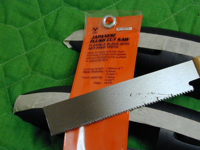
This Japanese flush cut saw look like just the right thing. Much like a razor saw or fret saw the
teeth of the flush cut saw have very little kerf, but with much larger teeth. The main drawback I could
see was the lack of a back, so the blade was very flexible, which might make it more difficult to
cut a straight line.
Teeth:
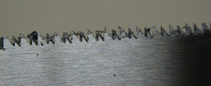
Here you see the teeth of the saw, and the lack of the typical pitch outward. Instead the teeth
are sharpened with bevels formed on there inner surface. Lots of shreds of plastic still of those
teeth.
Halving:
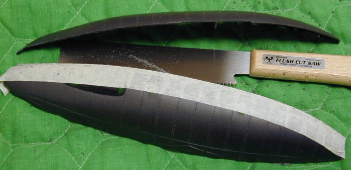
The cutting went quite well, straight and very fast. I would recommend this tool to anyone who
wants to do some kit bashing with plastic kits. Now the upper section of each side can be joined,
as well as those of the lower sections.
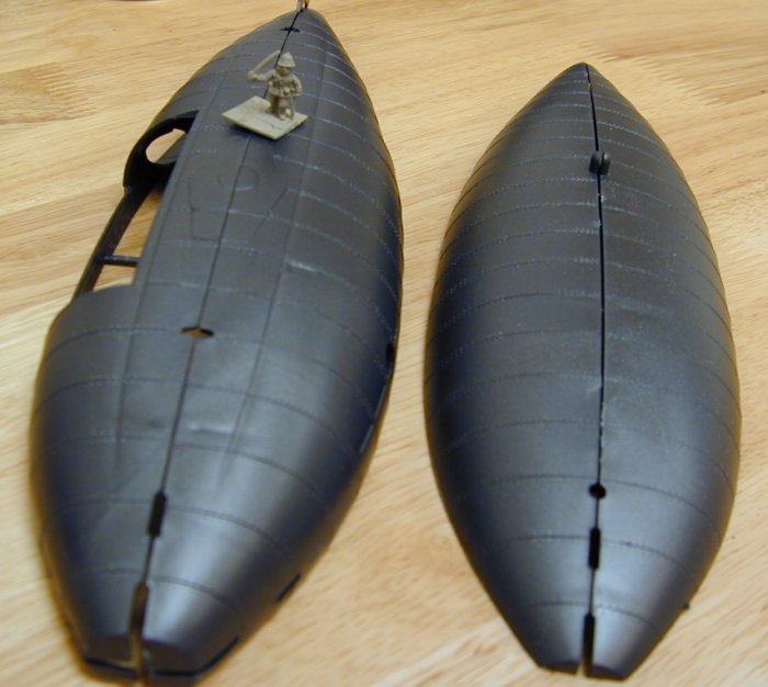
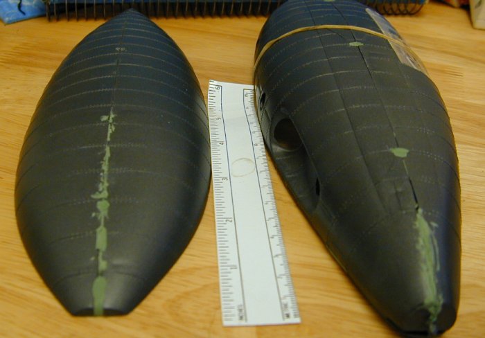
Size Check:
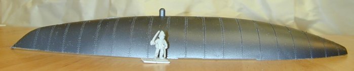
Here we see the original lower hull now as the upper hull of the proposed vessel.
A 15mm figure thrown in for some size comparison. The ship will be quite small is a
real scale model sense. But this is often for the best as it will take up less space
on the wargaming table. This kind of foreshortening is also use in buildings and landscape
features.
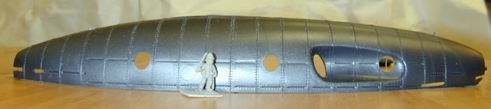
Here we see the original upper hull. The forward facing portholes will make nice ports
for guns or perhaps torpedo tubes.
Alignment:
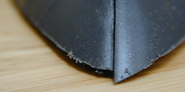
Even with careful cutting some misalignment is bound to occur.
Sanding:
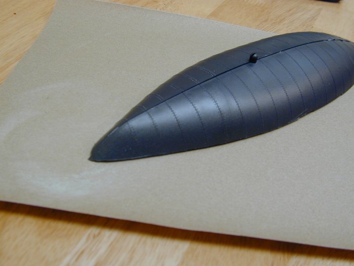
Some fine sandpaper and a flat surface is all the is really needed to correct the problem. As the
finished model will be sitting on flat surfaces, it is important to sand the entire bottom of
the parts and not just the ends. To do so would result in a gap at the bow or stern and the
"water". Another fix would be to add a wake made of some modeling putty to cover the problem spot.
I may use this trick as well, this is especially easy if one mounts the model on a base plate.
For now some sandpaper and some work will take care of it. Be sure to shake the buildup of
plastic dust from the sandpaper often as it builds up quite quickly and slows your work.
Deck Crew:
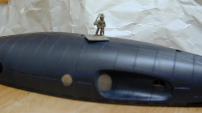
Here we see a, rather out of focus, 15mm figure on top of an upper hull. I am not planning on
having too many figures to act as deck crew from these models. A good thing too, as it
would get crowded rather quickly. It will be important to consider the size of the figures' bases
when planning out the decks. I will also want to leave space for deck guns and such.
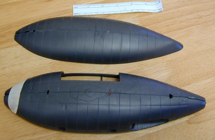
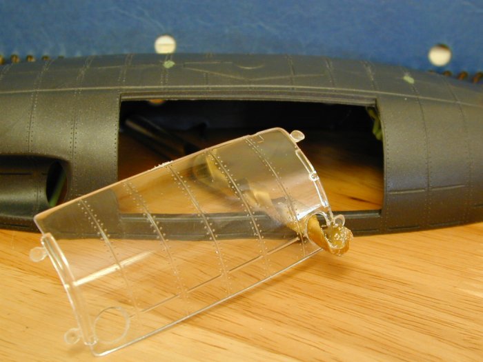
Comparison:
Here we see the two basic hulls that result from our work thus far.
The large gap seen in one hull is to be filled by one of the clear parts of the original
kit. Also lots of slots for additional parts, such as fins. I will be filling most of
these in as the Iron Rams are not intended to submerge, so there is no need from such
structures on the deck.
Gluing:
Time to start assembly: This is a "Snaptite" model and was intended to be assembled without glue.
This would not hold up very under our use, so good old model glue is the way to go. I found that the
model is rather strange in this respect. The alignment pins and holes tent to explode when glued.
One could use a glue that does not melt the plastic (such as cyanoacrylate) but I just pressed on.
The model parts are not a very good fit, so I used tape and rubber bands to help hold the joints until
they had a chance to solidify.
Bracing:
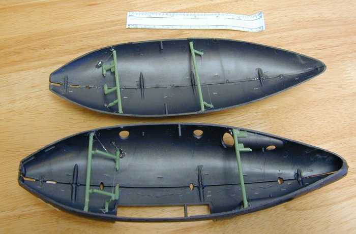
Cutting the hull in half left a much weekend structure. I may stick a base on latter, but to prevent
the hull from getting crushed while being picked up I will need to add some bracing. I just used
some plastic runners (also called "trees" or "sprue") to make some cross members. I just cut them
roughly to size and globbed on lots of old time airplane glue from Testers (the thick stuff).
This is really intended from making balsa models, but was universally use by all the kids in my
neighborhood when growing up to build plastic models. One could use hot glue or Duco or other space
filling glue, but I always have some Testers laying around. You can see the telltale strings of glue
in the photo above.
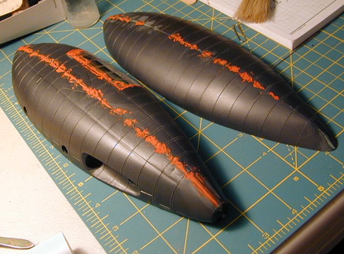
Filling the gaps:
The quality of the basic kit is quite poor, and the removal of the fins has left many gaps that need to be filled.
Here I have used "Squadron Green Putty", but "Bondo Glazing & Spot Putty" sold at Automotive shops or other filler
would do nicely. Look at the Science Fiction and Fantasy Model Madness Realm
for a nice discussion on fillers.
I mostly just pressed the putty from the inside out through the gaps and holes.
I press down from the outside at the same time to assure the putty fills the space well. This can
take a long time to fully dry, and tends to shrink. So a second application may be needed. We will
have to set it all aside to harden to the point where we can cut and sand the putty down to the models surface.
Drilling:
The original model had a large clear side panel to let one view the internal details. This will not
be needed in my model, but the port holes will. The clear panel had the port holes molded in, so I
needed to drill them out to match the other side. I found a size "Q" drill was the right size. I
started with a very small drill and worked my way up in size. Work slowly as the clear plastic is very
brittle.
Second Coat of Filler:
As the model comes along, the filling and sanding goes through several rounds. This time I used Bondo
spot putty because it was much more fluid them my 25 year old Squadron Green Putty. (I will talk about 30
year old paint later.)
First Prime:
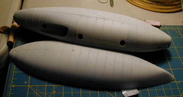
To check the quality of the filling job, I give the model a quick shot if primer. The white paint
helps ones eye to see the defects. To tell the truth, the matching of the parts is rather poor in
this model kit, so we will never get a museum quality model in the end. It is a good thing I am
a wargamer and not a fine scale modeler. The matte white paint also makes a good surface to draw
out plans for the superstructures and decks.
At this point I thought it best to divide this it to two separate projects.
I am planing on giving the small hull a traditional deck,
to view its progress proceed to The Smaller Ram.
To view the progress on the larger hull which I plan something more exotic
proceed to The Larger Ram.
To return to The Building How To page, simply click here.
To see the finial models go to me Battles page VSF Battles.
Or you can go to the Model Gallery Page.
Or to head back to the The Victorian Science Fiction Page.
For more inspiration go to my Victorian Inspiration page or
theMajor General's.
or THE AFRIBORIAN CAMPAIGN. pages.
I hope to be able to add more latter.
Thank you for looking:
DyeHard
![]()


|Over All Home
|What's New
|VSF Home
|My Other Hobbies|
|E-mail|

This work is licensed under a Creative Commons License.